

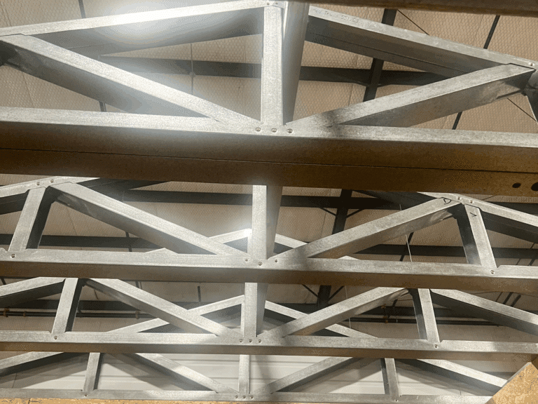
Framing delays, failed inspections, and field rework often start with missing or poorly coordinated cold-formed steel framing details. When connection requirements, deflection conditions, or load paths get overlooked early, crews lose time correcting avoidable problems in the field.
At Symmtrex, we help contractors and developers coordinate cold-formed steel framing details that support faster installation, cleaner inspections, and more predictable project schedules. Clear detailing improves structural performance, reduces framing conflicts, and helps crews keep projects moving without unnecessary revisions.
This guide breaks down the core components, drawing conventions, connection requirements, and field coordination issues that affect cold-formed steel framing projects. You’ll also see where detailing mistakes most often occur and how to review framing conditions before they cause costly delays.
Core Components And Terminology
Cold-formed steel framing relies on a specific set of members and material designations. When everyone on the team understands what each piece does and how to specify it, both drawings and field work move more efficiently.
Studs, Tracks, And Joists
You’ll work with studs, tracks, and joists more than anything else. Studs are vertical C-shaped members used in wall assemblies. They fit into tracks, which are U-shaped channels installed at the top and bottom of the wall frame. Tracks guide the studs and transfer loads at both ends.
Joists run horizontally and support floors or roofs. They span between ledger tracks or rim members and carry gravity loads. Bridging and blocking install between joists to control rotation and improve lateral stability. Openings use cripple studs, jack studs, and king studs.
Boxed headers built from back-to-back C studs span over doors and windows. Once you get comfortable with these terms, reading drawings and coordinating with crews becomes much easier.
Gauge, Thickness, And Coatings
Cold-formed steel framing members now use mil thickness designations instead of older gauge numbers, although legacy documents still reference gauge sizing. Teams often confuse 33 mil (20 gauge) non-structural studs with 54 mil (16 gauge) or heavier structural members.
Structural framing usually starts at 33 mil and increases to 118 mil or more for load-bearing applications. Steel thickness directly affects load capacity, screw pull-out values, and welding performance.
Thinner members buckle and cripple more easily when crews ignore detailing requirements. Coating matters just as much as thickness.
Most structural cold-formed steel framing uses hot-dip or mill-galvanized coatings to at least G60 or G90 per ASTM standards. In high-humidity or coastal environments, G90 or higher helps reduce corrosion risks at connections and cut edges.
Reading Structural Intent In Drawings
Cold-formed steel framing drawings contain a large amount of information through symbols, notes, and load diagrams. When you read them accurately, you reduce RFIs and improve coordination between design and field crews.
Load Paths And Bearing Conditions
Every detail in a cold-formed steel framing set exists to transfer load from one location to another. When reviewing a wall section or connection detail, ask where the load originates and where it transfers.
Gravity loads move down through studs into tracks and then into the floor or foundation. Lateral loads from wind or seismic activity transfer through shear walls and diaphragms into the foundation.
At bearing points, studs carry axial load through the web. If you see flange connections or eccentric loads, the detail must address bending conditions. Web stiffeners or nested studs should be present at heavy-load points. If they’re missing, treat that as a warning sign.
Non-bearing walls require different details from load-bearing walls. Deflection tracks at the top of non-bearing walls allow movement above without transferring structural loads into the partition.
Symbols, Notes, And Callouts
Cold-formed steel framing drawings use standardized shorthand for member designations. A callout such as 600S162-54 identifies a 6-inch-deep stud with a 1-5/8-inch flange and 54-mil thickness.
Once you understand the notation system, plan review becomes much faster. Keynotes and general notes often contain screw patterns, spacing requirements, and coating specifications that do not appear in section details.
Structural notes may reference AISI S240 or S400 standards, which govern design and installation requirements. Details typically include bubble references tied to a specific sheet and detail number.
If a detail is missing or a callout does not match, flag the issue before framing starts.
Connection Design Considerations
Cold-formed steel framing connections behave differently from hot-rolled steel connections because the material remains thin and susceptible to localized failures. Fastener selection and connector hardware both play major roles in system performance.
Fasteners, Screws, And Anchors
Self-drilling screws remain standard for cold-formed steel framing. Screw size and type depend on the thickness of the steel being connected.
Number-8 screws commonly support lighter framing, while number-10 and number-12 screws handle heavier structural framing. In steel-to-steel applications, the screw must drill through both layers without pre-drilling.
Screw spacing and patterns are never arbitrary. Shear wall details specify exact fastener locations at panel edges and within the field.
When crews change those patterns in the field, they also change the wall’s shear capacity. Power-actuated fasteners and pneumatic pins attach tracks to concrete or structural steel.
Always confirm that the fastener includes published load values for the substrate and base-metal thicknesses. Generic fastener substitutions can create failures at critical connections.
Clip Angles, Brackets, And Holdowns
Clip angles connect joists to walls, headers to king studs, and non-structural framing to floor systems. Most manufacturers publish load tables for their clips, and installers should follow those values unless the condition falls outside standard applications.
Holdowns and straps install at shear wall boundaries to transfer uplift forces into the foundation or floor system. Structural drawings usually specify the exact product and anchorage requirements.
If crews want to substitute products in the field, they should obtain engineering approval first. Bracket selection depends on load direction, magnitude, and steel thickness.
One of the most common inspection issues involves crews using non-structural brackets where structural brackets are required.
Wall, Floor, And Roof Interfaces
When different framing systems intersect, the details become more complex. Proper coordination at these transitions helps reduce cracking, leaks, and future service issues.
Head-Of-Wall And Deflection Conditions
The head-of-wall detail controls how a non-load-bearing partition connects to the structure above. In multi-story construction, the floor or roof structure above moves under load.
If crews rigidly attach the partition, the wall can crack or buckle as the structure shifts. Slotted deflection tracks at the top of the wall allow vertical movement while maintaining lateral restraint.
The slot length must match the expected structural deflection identified by the engineer. Using a standard track instead of a deflection track creates one of the most common and costly framing mistakes.
Floor Rim And Ledger Transitions
At floor levels, the rim track or rim board defines the edge of the framing system and provides bearing support for joists. In cold-formed steel framing, the rim usually consists of a continuous C or track member tied back to wall studs or blocking.
Ledger conditions occur when a floor system attaches to a wall instead of bearing directly on top of it. These conditions require a horizontal ledger member bolted or screwed to the studs, with joists supported by clips or hangers.
The stud wall must resist both axial and shear loads at these locations. Bearing stiffeners or nested studs at joist bearing points help prevent web crippling. Their placement should align with the joist layout, so crews must coordinate floor and wall framing drawings early.
Roof Edge And Parapet Framing
Roof edge and parapet details address lateral bracing, wind uplift, and waterproofing requirements in a single location. Parapet studs usually cantilever from the roof diaphragm and must resist out-of-plane wind pressure.
Coping and capping details require close coordination with roofing and waterproofing trades. The cold-formed steel framing must support cap flashing while allowing thermal movement that prevents cladding damage.
Roof edge connections to the top track also need to resist uplift loads, especially in high-wind regions. Strap ties or anchor clips with published uplift ratings commonly handle these conditions.
Coordination, Tolerances, And Field Fit
Even strong cold-formed steel framing designs must perform in real-world jobsite conditions where tolerances and trade coordination affect installation. Addressing coordination issues early helps keep the project on schedule.
Openings, MEP Penetrations, And Backing
MEP trades require openings throughout floors, walls, and roofs. In cold-formed steel framing, teams should locate and size every penetration before framing begins.
When crews cut flanges or webs in the field to fit ducts or piping, they weaken the member and often create expensive repair conditions. Framed openings in bearing walls require properly sized headers, jack studs, and king studs.
In non-bearing walls, cripple framing above and below openings maintains consistent alignment without introducing unnecessary load paths. Backing for grab bars, fixtures, and heavy equipment must be detailed and installed during framing.
Blocking plates, flat strap, or solid wood inserts can all work depending on the application. Teams should clearly identify backing locations on the drawings so installers do not miss them.
Dimensional Control And Alignment
Cold-formed steel framing remains dimensionally stable, but the supporting structure often varies beyond acceptable tolerances. Concrete slabs and structural steel commonly contain more variation than cold-formed steel framing systems allow.
Before framing starts, survey the substrate and identify high or low areas. Shim or grout tracks to correct minor elevation variations.
If crews discover major discrepancies, they should involve the structural engineer before continuing work. Trying to correct large floor deviations with field screw adjustments rarely works.
Plumb and level checks should continue throughout framing instead of waiting until the end of the project. Correcting alignment issues before drywall or sheathing installation saves time and reduces finish problems.
Common Failure Points And Review Checks
Field problems in cold-formed steel framing usually trace back to missing details, misread drawings, or coordination gaps between trades. Knowing where to review conditions early can save significant time and cost.
Frequent Detailing Errors
Using non-structural members in structural locations remains one of the most common framing mistakes. This issue typically occurs when crews substitute available material or when drawings fail to clearly distinguish structural from non-structural members.
Member designations should remain clear on every structural detail. Missing bearing stiffeners at heavy load points often lead to web crippling failures. Crews sometimes skip stiffeners because the detail appears acceptable without them. Any location where joists, beams, or concentrated loads bear on a stud web requires proper stiffening.
Inadequate screw patterns at shear walls and diaphragm chords continue to create inspection issues. The engineer’s specified screw pattern is a requirement, not a suggestion.
If crews want to change those patterns, they should obtain formal engineering approval before making modifications.
Shop Drawing Review Priorities
When reviewing shop drawings for cold-formed steel framing, first verify member designations and connection details. Pay close attention to substitutions or field modifications proposed by the contractor.
Do not rely only on appearance. Confirm that substituted members provide equivalent or greater section properties.
Review every deflection track location carefully. Slot lengths should match the design documents rather than field convenience. Examine anchor and holdown layouts against the structural drawings and identify any conflicts with field conditions.
Shop drawings should also reflect the latest architectural updates, including revised openings and MEP coordination changes. Outdated shop drawings often create avoidable field conflicts and installation delays.
Coordinate Your Framing Details Before Installation
Accurate cold-formed steel framing details help crews avoid field modifications, reduce inspection issues, and keep structural framing aligned with the project schedule.
Symmtrex manufactures engineered framing systems for contractors, developers, and builders who need reliable panel layouts, connection coordination, and fabrication support before installation starts.
If you’re preparing for a multifamily, commercial, modular, or residential framing project, get a quote, call (469) 842-7794, or tell us about your project so we can review your framing requirements before fabrication begins.
Frequently Asked Questions
What are cold-formed steel framing details?
Cold-formed steel framing details are technical drawings and specifications that show how steel studs, tracks, joists, connections, and framing interfaces should be installed. These details define load paths, fastening patterns, deflection requirements, and connection methods that crews follow during construction.
Why do cold-formed steel framing details matter on commercial projects?
Accurate cold-formed steel framing details help reduce framing conflicts, failed inspections, and field modifications. They also improve coordination between structural, architectural, and MEP trades so crews can install framing systems more efficiently.
What causes failures in cold-formed steel framing systems?
Most failures happen because crews miss structural details, substitute incorrect members, or install improper fastener patterns. Missing stiffeners, incorrect deflection tracks, and poorly coordinated penetrations also create common structural and inspection problems.
How do deflection tracks work in cold-formed steel framing?
Deflection tracks allow the structure above a non-load-bearing wall to move without transferring vertical loads into the partition wall. These tracks use slotted connections that maintain lateral stability while accommodating structural movement.
What is the difference between structural and non-structural steel studs?
Structural studs carry axial, lateral, or gravity loads and typically use heavier mil thicknesses such as 54 mil or greater. Non-structural studs mainly support drywall and interior partitions where load-bearing requirements do not apply.
How should contractors coordinate MEP penetrations in cold-formed steel framing?
Contractors should identify and size penetrations before framing begins so crews avoid cutting structural members in the field. Coordinating MEP layouts early helps maintain framing strength and reduces costly repairs or engineering revisions later in the project.
What should you review before approving cold-formed steel framing shop drawings?
Review member sizes, connection details, deflection track locations, screw patterns, and anchorage layouts before approving shop drawings. You should also confirm that the drawings reflect the latest architectural updates and MEP coordination requirements.
If you need help reviewing framing layouts or preparing engineered framing systems for your next project, you can always discuss your project requirements before fabrication and installation begin.